1 / 5
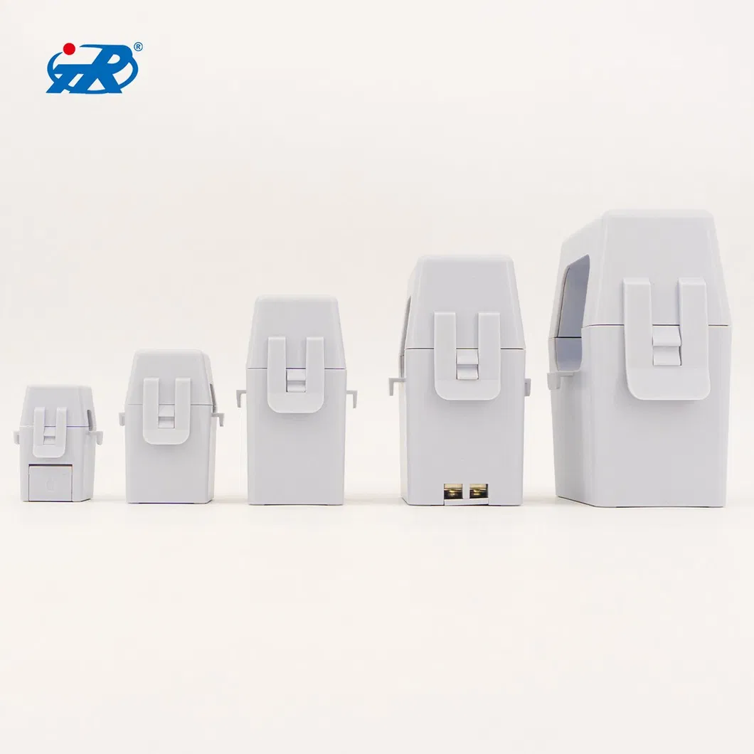
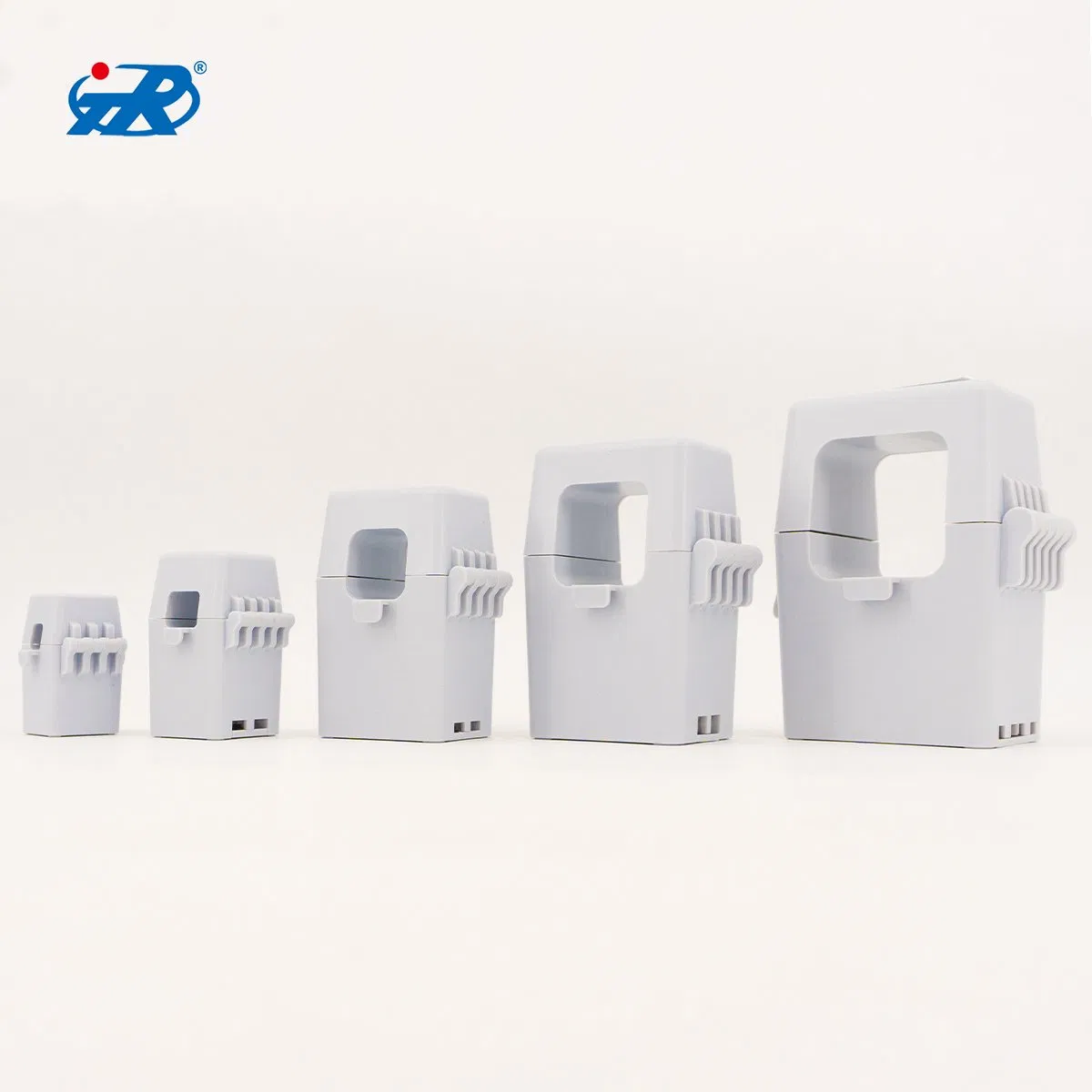
Rural power grid reconstruction project, Online environmental monitoring, Smart fire-fighting power consumption, Smart power consumption system, Power quality analysis and electrical equipment signal collection.
| Electrical parameters | |
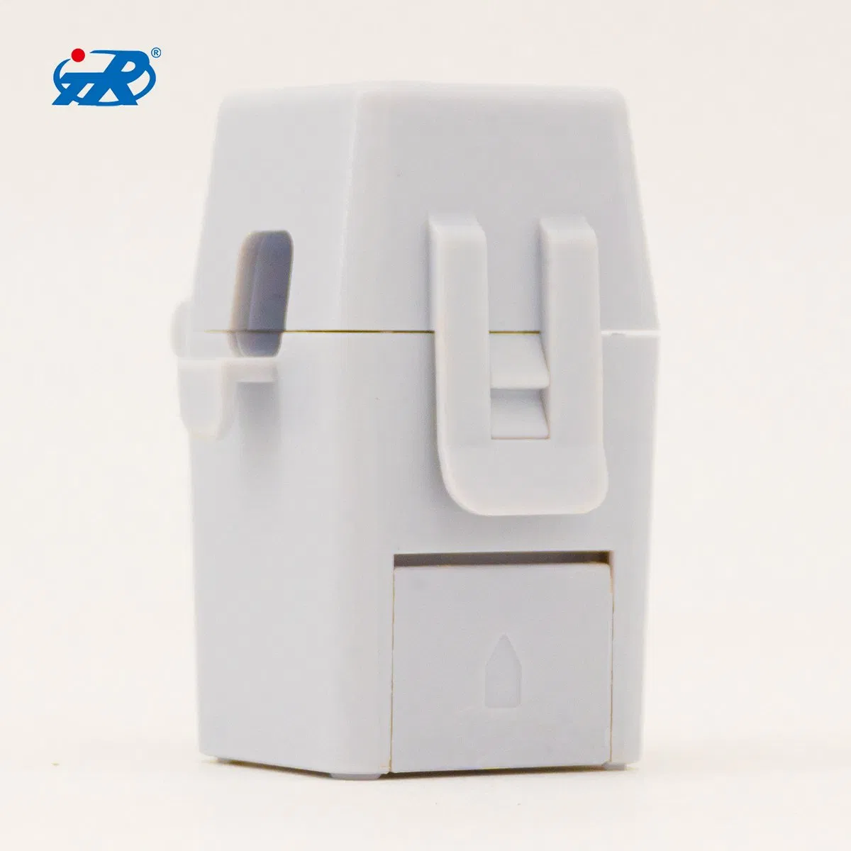
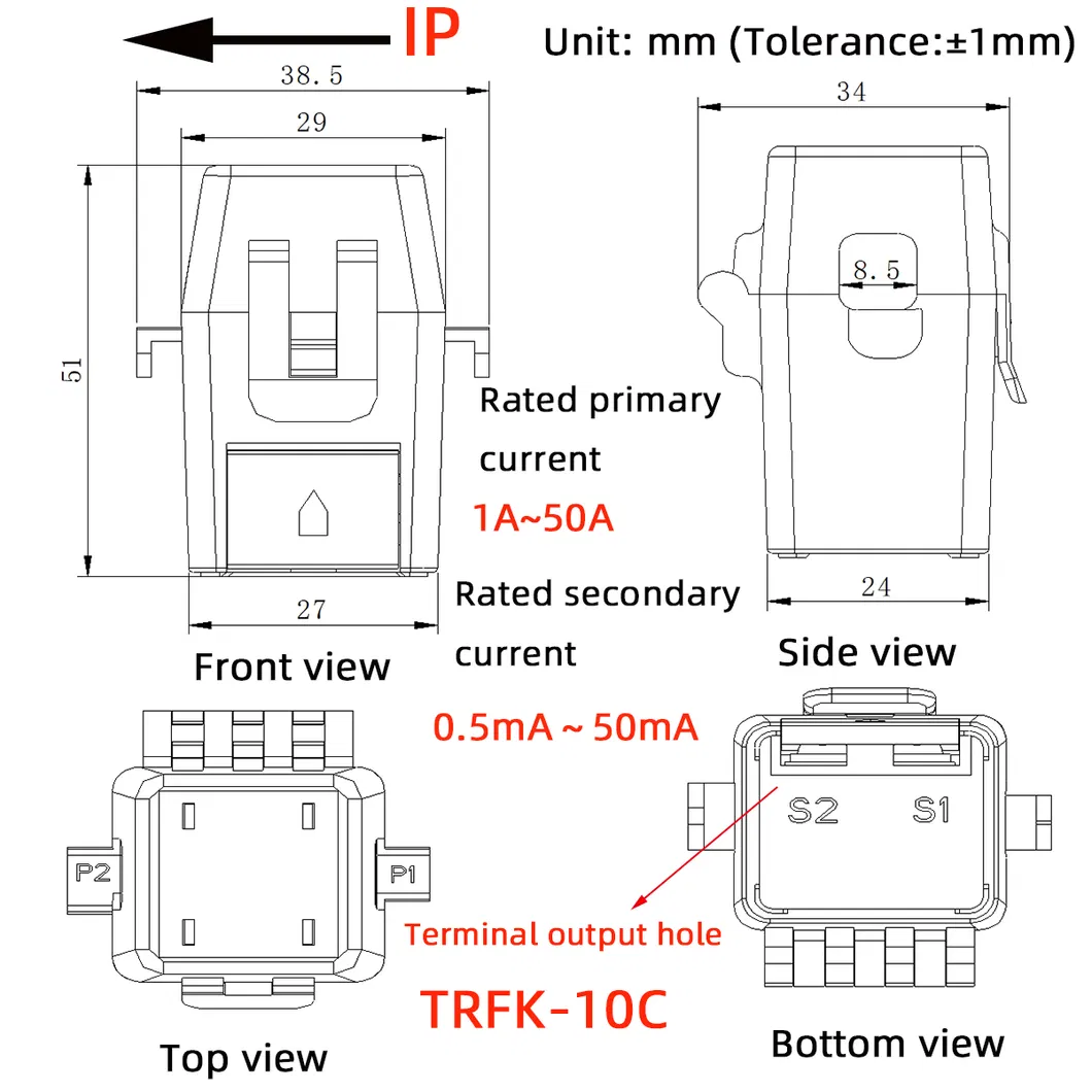
| Type | TRFK-10C |
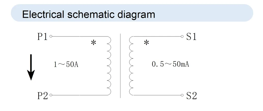
| Rated primary current | 1A~50A |
| Rated secondary current | 0.5mA~50mA |
| Overload | 1.2 times |
| Secondary load | ≤20Ω |
| Aperture | 8.5mm |
| Ratio error@rated primary | ±0.5%, ±1.0% |
| Phase error@rated primary | ≤150′ |
| Working frequency | 50/60 Hz |
| Rms voltage for AC isolation test | 3kV AC/1mA 10s |
| Operating ambient temperature | -25ºC~+75ºC |
| Weight | Around 130g |
| Accuracy parameters | |||||
| Input current(A) | 5%In | 20%In | 50%In | 100%In | 120%In |
| Ratio error(%) | ±0.75 | ±0.5 | ±0.5 | ±0.5 | ±0.5 |
| Phase error(′) | ≤180 | ≤150 | ≤150 | ≤150 | ≤150 |
Step 1: Before installing, ensure that the circuit is in the state of power failure, or live installation operation, professional personnel are required.
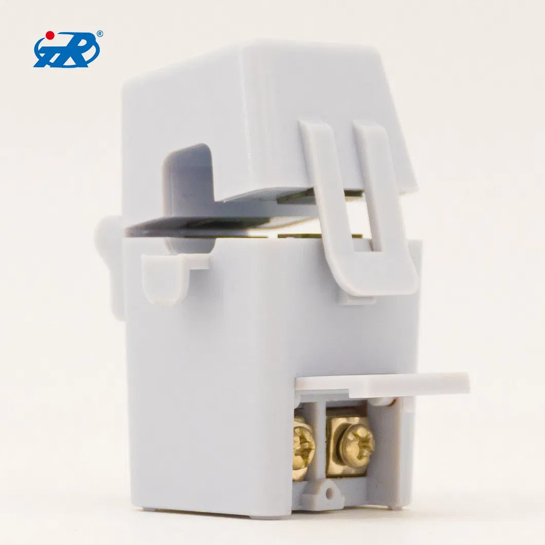
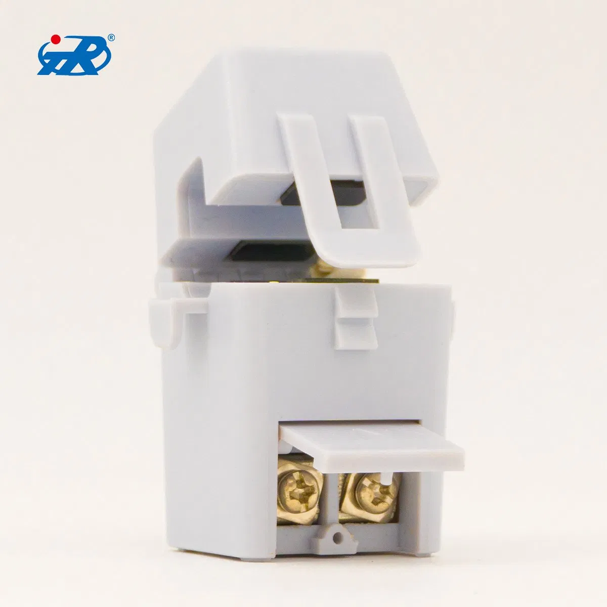
Step 2: Open the protective cover of current transformer, connect the wire with the terminal output of the current transformer and connect it to the port of the measuring equipment, and ensure the circuit is closed.
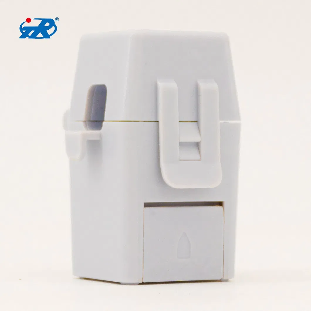
Step 3: Open the transformer latch and prepare for installation.
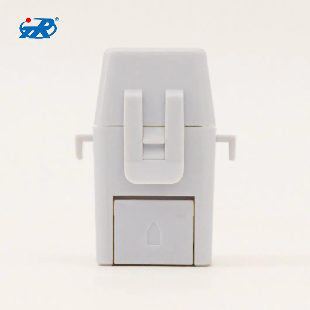
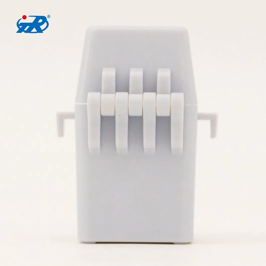
Step 4: Place the cable inside the hole of current transformer. Ensure that the current direction of the cable is consistent with the arrow on the current transformer. Lock the latch again, and fix the cable with the nylon ties to hook both ends of the transformer to prevent sliding.
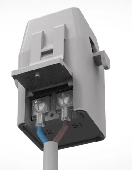
Fig.1: Connect S1 and S2

Fig.2: Open latch

Fig.3: Lock and fix