2026 Best PCB Mount vs Lead Wire Transformers How to Choose?

Time:2026-09-13 Author:Charlotte
0%

Selecting a transformer is rarely a simple matter of size and price. Engineers must match insulation, current capacity, thermal performance, mounting space, and safety requirements. The key question is not only How to choose between PCB mount and lead wire transformers, but also where the transformer will operate. A compact control board may favor PCB mounting. A vibrating enclosure may require flexible lead wires.

The International Energy Agency’s Electricity 2024 report expects strong electricity demand growth through 2026. This trend increases attention on efficient, reliable power conversion, even in small industrial and embedded systems. The U.S. Department of Energy’s 2024 distribution transformer rule also reinforces the importance of efficiency, although its scope does not cover every low-power PCB transformer. Different applications need different evidence.

Small details matter. Check the transformer’s VA rating beside the actual load, not the nominal label alone. Measure the enclosure temperature after continuous operation. Inspect creepage, clearance, fuse placement, and terminal strain relief. PCB mount units can reduce wiring and assembly time. Lead wire models can simplify remote placement and improve service access. Neither option wins universally.

The difficult part is accepting uncertainty. Datasheet temperatures may reflect controlled laboratory conditions, not a sealed cabinet beside a hot relay. Prototype testing can expose noise, heating, or mechanical weakness early. This guide compares both formats using manufacturer data, IEC 61558 safety principles, and practical design checks. It also challenges common assumptions, because the cheapest transformer may create higher assembly and maintenance costs later. Reliability is designed, measured, and sometimes reconsidered.
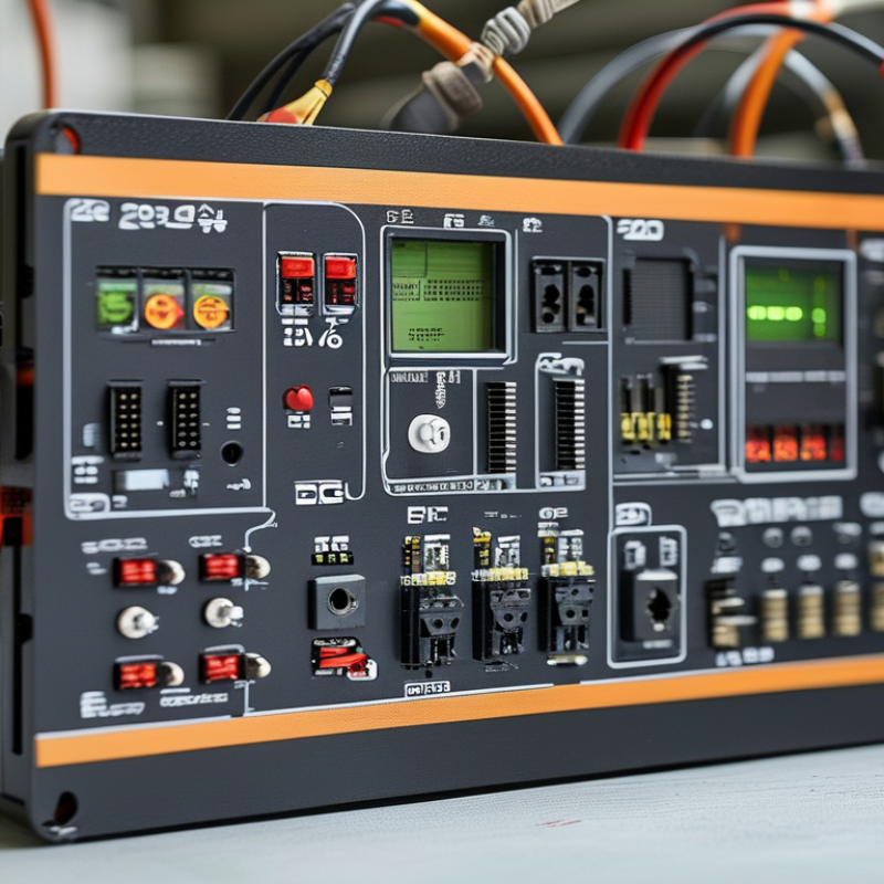
2026 Best PCB Mount vs Lead Wire Transformers How to Choose?

PCB Mount vs Lead Wire Transformers: Definitions and Basic Operating Principles

PCB Mount vs Lead Wire Transformers: Definitions and Basic Operating Principles

A transformer transfers alternating electrical energy through magnetic coupling. It normally uses two copper windings around a magnetic core. The input winding creates a changing magnetic field, while the output winding receives induced voltage. The turns ratio controls voltage conversion. More secondary turns usually produce higher voltage. Direct current does not support this continuous induction process.

PCB mount transformers have pins designed for direct soldering into a circuit board. Their compact bodies save wiring space and support consistent automated assembly. The board carries both mechanical support and electrical connections. Lead wire transformers use flexible wires instead. Installers connect these wires to terminals, connectors, or solder points. This arrangement allows more freedom when the transformer sits away from the main board.

That gap matters. PCB mounting can shorten connection paths and reduce assembly variation, but board material and solder joints must withstand heat and vibration. Lead wires simplify repositioning, although loose routing may increase noise pickup or create strain at the connection. A practical check includes voltage, current, insulation, frequency, mounting space, and required isolation distance. Never judge suitability by size alone. Heat tells a story. Undersized windings may overheat during continuous operation, even when initial testing appears normal. The distinction also becomes less clear in custom assemblies, where a leaded transformer may connect through a small adapter board.

Key Differences in Design, Installation, and Electrical Performance

PCB Mount vs Lead Wire Transformers: Design, Installation, and Electrical Performance

Choosing between PCB mount and lead wire transformers starts with the equipment’s physical design. PCB mount models use pins that enter prepared circuit-board holes. They save space and support automated assembly. However, their fixed position can complicate repairs or late design changes. Lead wire transformers connect through flexible insulated wires. This allows placement away from hot components, crowded boards, or vibrating panels. That flexibility matters.

During installation, PCB mount parts need accurate hole spacing and controlled soldering. Excessive heat can damage nearby pads or weaken the board. Lead wire versions require proper stripping, crimping, or terminal connections. The wires also need strain relief. Otherwise, repeated movement may stress the transformer terminals. I once treated wire length as a minor detail. That assumption was wrong. Longer wires can increase routing difficulty and create avoidable noise paths.

Electrical performance depends on more than the transformer type. Engineers should check rated voltage, frequency, insulation, temperature rise, and load behavior. PCB mounting usually creates short connections, which can reduce stray resistance and simplify grounding. Lead wires may introduce small voltage drops, especially when they are thin or unusually long. Measure it under the real load. Do not rely only on the label. Thermal spacing also affects reliability. A compact PCB layout may look efficient, yet trapped heat can shorten service life. Lead wires offer placement freedom, but careless routing can weaken insulation clearance. The practical choice often changes after testing the enclosure, not just the schematic.

How to Compare Safety, Reliability, Size, Cost, and Maintenance Needs

2026 Best PCB Mount vs Lead Wire Transformers: How to Choose?

Compare safety before size. PCB-mount transformers save board space and reduce wiring errors. However, their pins face solder-joint stress, vibration, and thermal cycling. Lead-wire transformers need more enclosure volume, but wires tolerate layout changes and simplify field replacement. Check insulation class, creepage, clearance, dielectric strength, and temperature rise against IEC 61558 requirements. Small does not mean safer.

Reliability depends on the assembly, not only the transformer. A PCB unit suits controlled, low-vibration equipment with stable production testing. A lead-wire unit works better where technicians may replace parts beside a cramped panel. The U.S. Department of Energy’s 2024 distribution-transformer analysis projects 3.6 quadrillion Btu in cumulative savings over 30 years. That report covers larger transformers, but it reinforces a useful point: efficiency losses deserve measurement, even in compact designs. Measure standby heat at the actual load.

Cost comparisons often miss maintenance. PCB mounting can lower labor and connector costs during volume production. Lead wires may reduce service time when access is poor. Review five-year costs, including solder inspection, cable routing, replacement stock, and downtime. My first selection once favored the smallest footprint. It passed electrical tests but trapped heat near adjacent components. That was a design mistake. Require thermal imaging, vibration checks, and sample-based pull testing before approval. Perfect assumptions rarely survive the first production run.

2026 Best PCB Mount vs Lead Wire Transformers: How to Choose?

Comparison of PCB-mount and lead-wire transformers across safety, reliability, size, cost, installation, and maintenance requirements
Comparison Dimension PCB-Mount Transformer Lead-Wire Transformer Selection Guidance
Typical Construction A compact transformer with pins or solder terminals designed to be inserted directly into a printed circuit board. A transformer with insulated flying leads, wires, or harness connections for attachment to a PCB, terminal block, connector, or chassis wiring. Choose the connection style that matches the assembly method, service strategy, and available mechanical space.
Best-Fit Applications
  • Compact power supplies
  • Control boards
  • Audio and signal circuits
  • High-volume electronic assemblies
  • Products with automated PCB assembly
  • Industrial control equipment
  • Chassis-mounted power systems
  • Retrofit and replacement work
  • Equipment with remote or separated wiring
  • Assemblies requiring field-replaceable wiring
PCB-mount versions generally suit integrated electronic assemblies. Lead-wire versions are often more flexible when the transformer and circuit board must be positioned independently.
Electrical Safety Safety depends on reinforced or basic insulation, creepage and clearance distances, dielectric strength, winding construction, PCB layout, and the end-product standard. Safety depends on the same transformer insulation requirements, plus wire insulation, strain relief, terminal spacing, routing, and protection against abrasion or accidental contact. Neither format is automatically safer. Verify the required working voltage, insulation system, dielectric test rating, creepage, clearance, and applicable end-product requirements.
Isolation Capability Can provide galvanic isolation between primary and secondary circuits when designed as an isolation transformer. The PCB layout must preserve the specified isolation barrier. Can provide the same galvanic isolation. Separate wires may make it easier to maintain physical separation between isolated circuits during installation. Confirm the isolation rating from the transformer documentation; mounting style alone does not determine isolation performance.
Thermal Performance Heat is transferred into the PCB, copper traces, nearby components, and surrounding air. Thermal performance can be affected by board material, copper area, airflow, and component spacing. Heat is transferred mainly through the transformer body, mounting surface, and surrounding air. The transformer can often be positioned away from heat-sensitive PCB components. Lead-wire construction may simplify thermal separation, while PCB mounting can be efficient in a compact, well-designed enclosure. Check temperature rise at the actual rated load.
Typical Temperature Rise The actual value varies widely with core size, power rating, insulation system, frequency, load, and enclosure airflow. Small low-power units commonly operate with noticeable surface heating under full load. Temperature rise is likewise design-dependent. Remote mounting may reduce the temperature experienced by the PCB, but it does not reduce the transformer’s own internal temperature rise. Use the manufacturer’s tested temperature-rise data rather than assuming that one mounting format always runs cooler.
Mechanical Retention Pins provide electrical and mechanical attachment, but larger or heavier transformers may require board supports, adhesive, brackets, or additional fixing points. Mechanical retention is normally provided by screws, clips, brackets, adhesive, or a dedicated mounting frame. Wires should not be used as the sole means of supporting the transformer. For equipment exposed to vibration or shock, evaluate terminal stress, mounting strength, wire strain relief, and compliance with the equipment’s mechanical requirements.
Vibration and Shock Resistance Can be reliable when the transformer is properly supported and solder joints are protected from excessive mechanical stress. Heavy components may place greater stress on the PCB. Can tolerate flexible installation, but unsupported wires may fatigue, rub against surfaces, or transfer force to solder joints and terminals. Lead-wire units are not automatically more rugged. The complete mounting system, wire routing, strain relief, and vibration profile must be evaluated.
Space and Package Efficiency Usually offers a clean, compact layout with no separate terminal block or wiring harness. The transformer must fit the board footprint and component-height limits. Requires additional space for wire bends, connectors, terminals, strain relief, and routing. It can save PCB area when the transformer is mounted outside the board. Select PCB mount for dense board-level integration. Select lead wire when placement flexibility is more important than minimum assembly volume.
Weight Distribution Concentrates transformer mass on the PCB. This may affect board deflection, connector loading, and transportation durability. Allows the transformer mass to be placed on the chassis or another structural surface instead of the PCB. Lead-wire construction is often preferable for heavier transformers or assemblies where the PCB cannot carry significant mechanical loads.
Installation Time Fast in automated production when the footprint, soldering profile, and board process are standardized. Manual replacement may require desoldering the transformer from the PCB. Installation can involve routing, stripping, crimping, soldering, connector insertion, and strain-relief work. However, wiring can be convenient during low-volume assembly or field installation. PCB mount usually has an advantage in repeatable, high-volume assembly. Lead wire can be advantageous when installation locations vary.
Manufacturing Automation Well suited to through-hole insertion and other controlled PCB assembly processes, provided the component dimensions and soldering requirements are compatible. More dependent on manual or semi-automated wire processing, including cutting, stripping, crimping, connector assembly, and inspection. For high-volume products, compare total process cost rather than component price alone. Labor and inspection can strongly affect the result.
Initial Component Cost Often economical in standardized, high-volume designs because the PCB provides both electrical interconnection and basic mounting. May require additional wire, terminals, connectors, clips, brackets, and strain-relief parts, increasing the total installed cost. Compare the complete bill of materials and assembly labor. A lower transformer unit price does not necessarily produce a lower system cost.
Total Installed Cost Commonly lower when the board is already designed for the transformer footprint and automated soldering is used. Can be competitive when the transformer is mounted remotely, when a common wiring harness is already used, or when field installation flexibility reduces redesign costs. Calculate transformer, PCB changes, connectors, wire processing, mounting hardware, labor, testing, and service costs together.
Repair and Replacement Replacement normally requires access to the PCB and may involve desoldering, board inspection, and solder-joint rework. Replacement can be simpler if the transformer is mechanically accessible and connected through serviceable terminals or connectors. Use lead-wire construction when field replacement is a major requirement. Use PCB mount when board-level replacement is acceptable and assembly compactness is the priority.
Maintenance Needs Routine maintenance is generally limited to visual inspection for discoloration, cracked solder joints, overheating, contamination, or PCB damage. Requires the same transformer inspection plus checks for loose terminals, damaged insulation, wire fatigue, chafing, corrosion, and inadequate strain relief. Lead-wire assemblies usually have more connection points to inspect. PCB assemblies may have fewer external connections but can be harder to repair.
Connection Reliability A correctly soldered pin connection is consistent and compact. Reliability can be reduced by poor soldering, board flexing, thermal cycling, or unsupported transformer mass. Reliability depends on crimp or solder quality, terminal retention, wire gauge, insulation, routing, and strain relief. More interfaces create more potential failure points. Use the connection method that minimizes joints and mechanical stress in the finished product, not merely during initial assembly.
Electrical Noise and EMI Considerations Short PCB connections can reduce loop area, but transformer placement may expose sensitive traces to magnetic fields. Layout, orientation, shielding, and filtering remain important. Longer leads can increase loop area and may pick up or radiate interference. Twisting appropriate wire pairs and separating power wiring from sensitive signals can help. Evaluate conducted and radiated noise in the complete assembly. Mounting style alone cannot guarantee electromagnetic compatibility.
Design Flexibility Lower flexibility after the PCB footprint, pin spacing, and transformer height have been finalized. Higher flexibility for transformer position, wire length, connector choice, and chassis arrangement, subject to voltage-drop, insulation, and noise limits. Choose lead wire when enclosure layout or future revisions are uncertain. Choose PCB mount when the design is stable and optimized for compact production.
Production Consistency High consistency is possible when the PCB footprint, soldering process, and inspection criteria are controlled. Consistency depends more heavily on wire length, stripping, crimp height, terminal insertion, routing, and operator or machine control. PCB mount generally offers simpler repeatability in a fixed product design; lead wire requires robust wiring-process controls.
Common Failure Risks
  • Overheating from overload or poor ventilation
  • Cracked solder joints
  • PCB damage from mechanical stress
  • Insufficient creepage or clearance
  • Incorrect pinout or footprint
  • Loose or incorrectly crimped terminals
  • Wire insulation damage
  • Inadequate strain relief
  • Incorrect wire routing or polarity
  • Insufficient separation between circuits
Apply design-for-reliability checks to the entire transformer assembly, including mounting, wiring, PCB layout, enclosure, and operating environment.
Expected Service Life Service life is governed mainly by insulation temperature, load, voltage, frequency, thermal cycling, vibration, and manufacturing quality—not by PCB mounting alone. Service life is governed by the same transformer factors, with additional effects from wire flexing, terminal corrosion, abrasion, and mechanical strain. Select a suitable temperature class, power margin, insulation system, and mechanical design. Avoid using nominal power ratings without thermal validation.
Recommended Choice Best for compact integrated products
  • Stable PCB architecture
  • High-volume production
  • Automated assembly
  • Limited service access requirements
Best for flexible or serviceable layouts
  • Remote chassis mounting
  • Heavy transformer assemblies
  • Field replacement requirements
  • Variable wiring or enclosure arrangements
Base the final choice on verified electrical safety, thermal testing, mechanical retention, production cost, and the required maintenance method.

Note: Ratings, dimensions, temperature rise, dielectric strength, insulation class, and compliance requirements vary by transformer design. Always verify the component datasheet and the applicable end-product safety standard before production release.

Quick decision rule: Choose a PCB-mount transformer when compact integration and automated assembly are the main priorities. Choose a lead-wire transformer when remote placement, mechanical flexibility, heavy-component support, or field serviceability is more important.

Choosing the Right Transformer for Different PCB and Wiring Applications

Choosing the Right Transformer for Different PCB and Wiring Applications

PCB mount and lead wire transformers solve different installation problems. PCB mount units fit directly into compact control boards, reducing assembly time and cable clutter. They suit sensors, timers, audio circuits, and low-power embedded equipment. However, their fixed pin layout can restrict insulation spacing and servicing access. Measure the board footprint carefully, not just the transformer body.

Lead wire transformers provide more placement freedom. Their wires can reach a terminal block, switch, or enclosure-mounted board. This option works well when vibration, heat, or mechanical separation affects the design. The extra wiring also creates possible failure points. Secure the leads, protect strain relief, and keep primary conductors away from low-voltage traces.

The U.S. Department of Energy has estimated annual distribution-transformer losses near 61 billion kWh in the United States. Small transformers do not create that entire impact, but efficiency still matters. Check no-load loss, temperature rise, insulation class, and rated frequency. IEC 61558 requirements help evaluate safety and isolation, while IPC-2221 guidance supports practical PCB spacing decisions. In testing, engineers often discover that a smaller transformer runs hotter than expected. That is easy to miss. Leave ventilation space, confirm the real load, and test under continuous operation rather than a brief bench measurement.

2026 Best PCB-Mount vs Lead-Wire Transformers: How to Choose

Representative upper-end continuous power ratings by application. Actual ratings vary by voltage, insulation class, thermal design, frequency, and manufacturer specifications.

How to choose: PCB-mount transformers are generally suited to compact, low-to-moderate power control and isolation circuits with direct board integration. Lead-wire transformers are typically preferred when higher power, flexible positioning, easier replacement, or greater wiring clearance is required.

Step-by-Step Selection Criteria for Your Project Requirements

2026 Best PCB Mount vs Lead Wire Transformers: How to Choose?

Step-by-Step Selection Criteria for Your Project Requirements

Define the electrical load before comparing package styles. Record input and output voltage, VA rating, frequency, duty cycle, and allowable temperature rise. Do not size from nominal voltage alone. Startup current may briefly exceed the operating value. The first estimate may be wrong.

Measure twice. Space matters. Check the board footprint, pin spacing, enclosure height, and nearby heat-sensitive parts. A PCB mount transformer suits compact assemblies with fixed wiring and controlled production. Verify creepage, clearance, insulation class, and board material with the applicable safety requirements. Examine the datasheet carefully, including derating curves and thermal test conditions.

Choose lead wire construction when wiring flexibility, field replacement, or vibration isolation matters. Inspect wire length, insulation temperature rating, termination method, and strain relief. In a practical enclosure, leave enough bending radius around each lead. Avoid routing transformer wires beside sensitive signal traces when magnetic noise could affect performance. Mounting holes and mechanical support deserve equal attention. A heavy transformer can stress solder joints during transport. Test the selected part at maximum load, repeated startups, and the enclosure’s real ambient temperature. Listen for unexpected hum. Record failures, even minor ones, because early testing often reveals assumptions that calculations miss.

FAQS

What is the basic function of a transformer?

A transformer transfers alternating electrical energy through magnetic coupling. Two copper windings surround a magnetic core. The turns ratio controls voltage conversion. Direct current does not support continuous induction.

What is a PCB mount transformer?

It has pins that solder directly into prepared circuit-board holes. The board provides electrical connections and mechanical support. Its compact body reduces wiring space and supports automated assembly.

What is a lead wire transformer?

It uses flexible insulated wires instead of soldering pins. Installers connect the wires to terminals, connectors, or solder points. This allows placement away from the main circuit board.

When is PCB mounting a practical choice?

PCB mounting suits compact control boards, sensors, timers, and embedded equipment. Short connections can reduce wiring variation and stray resistance. Check hole spacing carefully.

When are lead wires more useful?

Lead wires help when heat, vibration, or crowded boards affect placement. They can reach a terminal block or enclosure-mounted board. Flexible placement helps.

What installation problems can PCB transformers create?

Incorrect hole spacing can prevent proper insertion. Excessive soldering heat may damage pads or nearby components. Fixed positioning can also complicate repairs and later design changes.

What installation problems can lead wires create?

Long wires may increase noise pickup and routing difficulty. Thin wires can cause voltage drops under real load. Secure the leads and add strain relief. Loose routing is risky.

Which electrical details should engineers compare?

Compare rated voltage, frequency, current, insulation, temperature rise, and load behavior. Also check isolation distance and mounting space. Do not judge suitability by size alone.

How can heat affect transformer reliability?

An undersized winding may overheat during continuous operation. A short bench test may look normal. Heat tells a story. Test inside the real enclosure with ventilation limits.

Can a lead wire transformer connect to a circuit board?

Yes. It may connect through terminals, solder points, or a small adapter board. The distinction becomes less clear in custom assemblies. Recheck clearances and mechanical support.

Conclusion

Choosing the right transformer begins with understanding the difference between PCB mount and lead wire designs. PCB mount transformers attach directly to a circuit board, offering compact integration, shorter connections, and efficient assembly for space-limited electronic products. Lead wire transformers connect through flexible wires, providing greater installation freedom and easier positioning when the transformer must be separated from the main circuit. Their electrical performance, insulation, thermal behavior, and connection method should be evaluated according to the application rather than by size alone.

How to choose between PCB mount and lead wire transformers depends on your project’s voltage, current, operating temperature, available space, assembly process, safety requirements, and maintenance expectations. Compare reliability, protection, cost, replacement access, and long-term service needs before making a decision. PCB mount models are often suitable for compact, repeatable designs, while lead wire versions can be better for adjustable layouts, higher clearance, or easier field wiring. A step-by-step review of electrical specifications, mechanical constraints, installation conditions, and compliance requirements will help ensure a safe and dependable choice.

Charlotte

Charlotte

Charlotte is a seasoned marketing professional with a deep understanding of the company's portfolio and a passion for elevating its presence in the market. With a keen eye for detail and a commitment to excellence, she ensures that our professional blog is regularly updated with insightful articles......