Voltage transformers rarely fail without warning. Their service life often declines through small, repeated stresses: heat, moisture, vibration, loose terminals, and inaccurate testing. A transformer that appears clean outside may still suffer from insulation aging or internal discharge. In 2026, reliable maintenance depends on measured evidence, not assumptions.
This guide explains How to extend the service life of voltage transformers through practical inspection, loading control, thermal monitoring, and disciplined testing. Technicians should review oil or insulation condition, examine connection points, and compare current readings with historical records. Infrared scans can reveal abnormal heating before visible damage appears. Manufacturers’ specifications and qualified engineering judgment must guide every maintenance decision.
Small details matter.
A cabinet door left partly open can allow dust and humidity to enter. Excessive secondary wiring loads can also increase measurement errors and thermal stress. Preventive work should follow documented procedures, calibrated instruments, and local electrical safety requirements. However, no maintenance plan is perfect. Field conditions change, records may be incomplete, and an early warning can be misinterpreted. That is why experienced teams verify unusual results, investigate repeated alarms, and reassess inspection intervals after every significant event. Careful maintenance cannot stop aging, but it can slow deterioration, improve measurement accuracy, and reduce unexpected outages. The following sections examine practical strategies for protecting voltage transformers throughout their operational life.
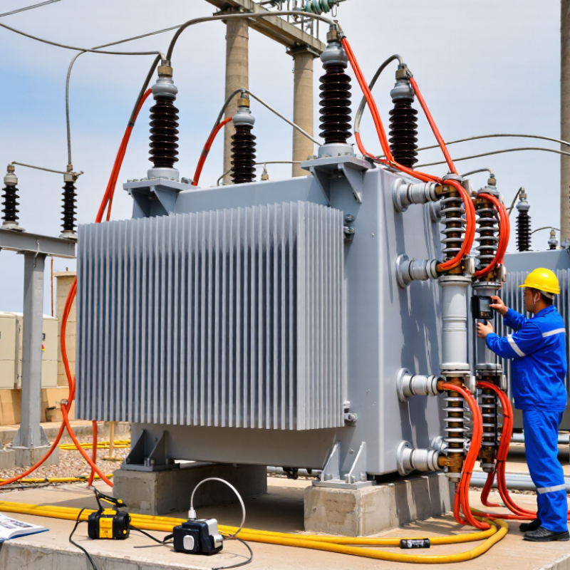
How to Extend Voltage Transformer Service Life in 2026?
A voltage transformer, or VT, reduces high voltage to a measurable secondary value. It supports metering, protection relays, and system isolation. Its service life means more than years in operation. It also covers accuracy, insulation strength, thermal stability, and safe performance under faults.
Typical VTs serve for 20 to 30 years. Some remain reliable beyond 40 years. The U.S. Department of Energy’s Transformer Resilience and Advanced Components report describes a broader transformer fleet with many units operating for 30 to 40 years. However, that figure does not guarantee the same life for every VT. CIGRE Technical Brochure 642 links transformer failures with insulation, bushings, connections, and aging accessories. A neat number can mislead.
IEC 61869-1:2023 and IEEE C57.13-2016 emphasize accuracy, insulation, and testing requirements. In practice, technicians should inspect secondary terminals, grounding points, oil levels, and cabinet heaters. Look for cracked porcelain, brown insulation, loose wiring, or moisture near the cable gland. Measure insulation resistance and ratio accuracy during planned outages. Thermal imaging can reveal a hot terminal before visible damage appears. Keep dust away from ventilation paths. Control burden on the secondary circuit, because excessive burden can reduce measurement accuracy. I have seen maintenance plans focus on age while ignoring vibration and condensation. That is a weakness. A 25-year-old VT in a clean indoor panel may outperform a newer unit exposed to salt, heat, and repeated switching.
Voltage transformer service life is commonly planned within a 20–40 year range, depending on insulation system, thermal stress, moisture control, loading, and maintenance quality. Regular insulation testing, oil analysis where applicable, terminal inspection, corrosion control, and surge protection can help detect deterioration before failure.
Typical service-life ranges: Oil-filled voltage transformers commonly serve for approximately 25–40 years, dry-type units for approximately 20–30 years, and gas-insulated units for approximately 30–40 years. Actual service life depends on operating conditions and maintenance history.
How to Extend Voltage Transformer Service Life in 2026?
Voltage transformer aging rarely begins with a dramatic failure. Heat, moisture, partial discharge, vibration, and repeated overvoltage slowly weaken insulation. Loose terminals can create hot spots inside an apparently clean cabinet. CIGRE Technical Brochure 642 reviewed 964 transformer failures from 58 utilities between 1996 and 2010. Its findings repeatedly identified insulation systems, bushings, connections, and overheating as important failure areas. Voltage transformers are smaller, but they face similar stresses.
Temperature deserves close attention. IEEE Std C57.91 explains that insulation aging accelerates sharply as operating temperature rises. A practical field rule often treats each 6–8°C increase as roughly doubling thermal aging. This is not a perfect prediction for every voltage transformer. It remains a useful warning. Measure enclosure temperature, inspect ventilation, and check whether nearby equipment adds radiant heat. Moisture deserves equal respect. Condensation can enter through cracked seals, damaged breathers, or poorly closed cable glands. Partial-discharge testing can reveal defects before visible damage appears.
Tips: Record insulation resistance, secondary voltage, contact resistance, and temperature trends. Compare readings with previous records, not only factory limits. Clean dust carefully, tighten connections using specified torque, and investigate unusual noise or odor. Do not assume a normal ratio test proves complete health. A spotless surface can still hide internal deterioration. Review results against IEC 61869 requirements and qualified maintenance procedures. The uncomfortable truth is simple: many failures are noticed late because inspections focus on appearance.
| Aging or Failure Factor | Typical Stress or Warning Level | Main Failure Mechanism | Recommended Inspection or Test | Life-Extension Action | Suggested Review Interval |
|---|---|---|---|---|---|
| Thermal Overloading | Persistent winding or oil temperature above the equipment design limit; repeated operation near rated burden | Accelerated insulation deterioration, increased winding resistance, and loss of dielectric strength | Load survey, infrared thermography, winding-resistance measurement, and temperature-trend review | Reduce unnecessary burden, improve ventilation, correct loose connections, and keep cooling paths clean | Temperature review monthly; thermography at least annually |
| Excessive Ambient Temperature | High enclosure temperature, direct solar heating, or inadequate ventilation | Higher insulation aging rate and reduced cooling efficiency | Measure ambient and enclosure temperatures during peak operating periods; inspect ventilation openings | Provide shading where appropriate, maintain airflow, and prevent blocked louvers or filters | Seasonal inspection and after major enclosure modifications |
| Moisture Ingress | Visible condensation, damaged seals, high humidity, or declining insulation-resistance values | Reduced insulation resistance, surface tracking, corrosion, and partial discharge risk | Visual inspection, insulation-resistance test, power-factor or dissipation-factor test, and seal inspection | Repair gaskets and cable entries, control condensation, replace damaged breathers, and keep enclosures dry | Inspect every 6–12 months and after severe weather or flooding |
| Electrical Transients and Lightning | Frequent switching surges, lightning exposure, or inadequate surge-protection coordination | Inter-turn insulation puncture, flashover, or damage to primary and secondary insulation | Inspect surge protective devices, grounding conductors, clearances, and event records; perform dielectric tests when required | Maintain coordinated surge protection, minimize unnecessary switching, and verify low-impedance grounding paths | Annual inspection and immediately after major surge events |
| Overvoltage and Ferroresonance | System voltage above the transformer rating or abnormal voltage during lightly loaded switching conditions | Core saturation, overheating, distorted waveforms, and insulation stress | Power-quality recording, waveform analysis, system-model review, and secondary-load verification | Use suitable damping or grounding arrangements, correct system settings, and avoid operating conditions known to trigger ferroresonance | Review after switching changes or abnormal voltage events |
| Excessive Secondary Burden | Connected burden exceeds the rated burden or long cable runs create excessive voltage drop | Ratio and phase-angle errors, additional heating, and inaccurate protection or metering | Calculate connected VA, measure secondary voltage, and verify cable length, conductor size, and terminal tightness | Remove unnecessary devices, shorten or upsize secondary wiring, and keep connections secure | Verify during commissioning and after every secondary-circuit change |
| Loose or Corroded Connections | Discoloration, abnormal heating, oxidation, vibration-related looseness, or unstable readings | Localized hot spots, arcing, measurement error, and eventual terminal failure | Torque verification, visual inspection, infrared thermography, and continuity testing | Clean or replace affected hardware, apply approved connection practices, and control vibration | At least annually and during planned outages |
| Contamination and Surface Tracking | Dust, salt, industrial deposits, bird contamination, or wet conductive deposits on insulation surfaces | Leakage current, surface discharge, flashover, and progressive insulation erosion | Visual inspection, ultraviolet discharge inspection where applicable, and surface-cleanliness assessment | Clean using an approved procedure, improve enclosure sealing, and increase inspection frequency in polluted environments | Every 6–12 months; more frequently in coastal or industrial areas |
| Mechanical Vibration and Shock | High vibration from nearby machinery, transport damage, loose mounting, or seismic movement | Cracked insulation, loosened terminals, winding displacement, and seal damage | Check mounting hardware, enclosure condition, vibration levels, and post-event electrical test results | Secure mounting, correct alignment, install suitable vibration isolation, and inspect after transport or seismic events | Annual inspection and after abnormal mechanical events |
| Insulation Deterioration | Increasing test-loss values, declining insulation resistance, unusual odor, noise, or discharge activity | Thermal, electrical, and chemical degradation leading to internal breakdown | Trend insulation resistance, dissipation factor, partial discharge, and oil quality where applicable | Remove the transformer from service for specialist assessment when test trends deteriorate rapidly or exceed applicable limits | Baseline at commissioning; repeat testing according to condition and criticality |
| Oil Quality Degradation (Oil-Immersed Units) | High moisture, acidity, gas generation, sludge, or reduced dielectric breakdown strength | Loss of insulation performance, overheating, internal arcing, and accelerated paper aging | Oil sampling and laboratory analysis, including moisture, acidity, dielectric strength, and dissolved-gas analysis when appropriate | Repair leaks, filter or reclaim oil when technically justified, and investigate abnormal gas patterns | Annually for critical units; otherwise according to risk assessment |
| Poor Grounding and Shielding | High ground impedance, ground-loop noise, or inadequate shielding of low-level secondary circuits | Surge damage, interference, incorrect readings, and increased touch-potential risk | Ground-continuity and earth-impedance checks; inspect cable shields and single-point grounding arrangements | Correct bonding, maintain suitable shielding, and eliminate unintended parallel return paths | Annual verification and after grounding-system alterations |
How to Extend Voltage Transformer Service Life in 2026?
Routine inspection remains the most practical protection against early voltage transformer failure. CIGRE Technical Brochure 642 reviewed 964 transformer failures and identified insulation, winding, and bushing defects as major contributors. Maintenance teams should inspect terminals, porcelain surfaces, grounding points, and enclosure seals during each planned outage. Look for oil stains, cracked insulation, corrosion, loose hardware, and unusual heating marks. Small details matter.
Record secondary voltage, load conditions, ambient temperature, and alarm history. Compare each reading with previous records, not only factory limits. Infrared scans can reveal abnormal temperature differences around terminals and connections. Oil-filled units may require dielectric strength, moisture, acidity, and dissolved-gas testing. IEC 61869-3 provides important requirements for instrument transformer performance, but field conditions still demand engineering judgment.
Keep inspection intervals risk-based. A heavily loaded or polluted installation deserves more frequent checks than a clean indoor unit. Verify test instruments before measuring. Otherwise, accurate-looking data may mislead decisions. Replace damaged gaskets promptly, remove surface contamination carefully, and confirm grounding continuity. Preventive maintenance should also include functional checks of fuses, disconnectors, and protection circuits. Do not ignore repeated minor alarms. They may indicate moisture ingress, insulation deterioration, or a developing connection fault.
A weakness remains common: records are often incomplete. Without reliable trends, maintenance becomes guesswork. CIGRE reliability findings support disciplined condition monitoring, but every site should adjust procedures to climate, age, loading, and operating history.
Extending a voltage transformer’s service life in 2026 depends on controlling heat, moisture, and fault energy. CIGRE Technical Brochure 642 analyzed 964 transformer failures and identified insulation systems, bushings, and connections as recurring weak points. That evidence supports a practical maintenance focus: inspect the hottest zones, not only the nameplate readings.
Cooling needs simple discipline. Keep radiators, vents, and cabinet filters clean. Measure winding or oil temperature during peak loading, especially after hot starts. IEEE C57.91 guidance links higher insulation temperature with sharply shorter life; the commonly used thermal rule suggests life can halve for each 6–8°C rise. Small details matter. A blocked vent may remain invisible until summer. Oil-filled units need periodic moisture and dissolved-gas testing, while dry-type units need airflow and surface cleaning. I would not treat one test as proof of good condition.
Electrical protection should prevent a small abnormality from becoming internal damage. Check primary fuses, surge arresters, grounding paths, and secondary wiring for looseness or corrosion. Verify relay settings against actual system fault levels. IEC 61869 requirements also reinforce accurate ratio, polarity, and insulation performance checks. Record trends, not isolated results. A single normal reading can mislead. In practice, maintenance teams sometimes replace protection devices without reviewing coordination, which leaves the transformer exposed. That mistake deserves review. Use infrared scans under load, compare phase temperatures, and investigate any growing imbalance before it becomes a failure.
Modern monitoring can reveal deterioration before a voltage transformer fails during a switching event. IEC 60076-7 reports that each 6°C increase in winding hot-spot temperature can approximately double paper-insulation aging. This figure mainly applies to oil-filled transformers, so engineers should not transfer it blindly to cast-resin units. That limitation matters.
A practical 2026 program combines infrared scans, online temperature sensors, insulation-resistance tests, and partial-discharge monitoring. IEC 61869-1 defines key requirements for instrument transformers, while IEEE C57.104 provides guidance for interpreting dissolved-gas data in oil-filled equipment. Trending is more valuable than one reading. A gradual rise in moisture, capacitance, or discharge activity deserves investigation, even when values remain within limits.
Digital records can link alarms with load, ambient temperature, humidity, and switching history. A 10-minute sampling interval may expose repeated thermal spikes that monthly inspections miss. Remote systems also reduce unnecessary site visits. However, sensors can drift, lose communication, or create false confidence. Human review remains necessary.
The uncomfortable truth is simple: more data does not guarantee better decisions. Maintenance teams should verify critical alarms with calibrated instruments and document each intervention. A small wiring error can imitate insulation failure. That risk is easy to underestimate.
Most voltage transformers operate reliably for 20 to 30 years. Some continue beyond 40 years. Age alone proves little.
Service life depends on accuracy, insulation strength, thermal stability, and safe fault performance. Heat, moisture, vibration, pollution, and switching stress can shorten it.
Inspect porcelain, terminals, grounding points, seals, and cable glands. Look for cracks, corrosion, oil stains, loose wiring, and brown insulation. Small marks matter.
Use a risk-based schedule. Polluted, outdoor, or heavily loaded units need more frequent inspections than clean indoor units. Fixed intervals can be too simple.
Measure insulation resistance and ratio accuracy during planned outages. Oil-filled units may need moisture, acidity, dielectric strength, and gas testing.
Yes. Thermal imaging can reveal a hot terminal or connection before visible damage appears. Compare similar points under similar loads.
Excessive secondary burden can reduce measurement accuracy. Check connected loads, wiring, terminals, and protection circuits. The reading may look normal but still drift.
Moisture can weaken insulation and encourage corrosion. Dust can block ventilation paths. Clean surfaces carefully, replace damaged gaskets, and inspect cable entries.
Record secondary voltage, load, temperature, alarms, and test results. Compare trends over time. Incomplete records turn maintenance into guesswork.
Consider replacement after repeated alarms, insulation deterioration, severe overheating, damaged porcelain, or unstable accuracy. A newer unit is not automatically better.
This article explains how to extend the service life of voltage transformers by combining proper operation, regular inspection, and preventive maintenance. It introduces the function of voltage transformers, defines their service life, and outlines typical lifespan expectations under different operating conditions. It also examines common causes of aging and failure, including excessive heat, moisture, insulation deterioration, electrical overload, mechanical stress, and loose connections.
The discussion then presents practical maintenance procedures, such as checking insulation resistance, monitoring temperature, inspecting terminals, removing dust, and identifying abnormal noise or vibration. It also explains how improved cooling, high-quality insulation management, grounding, surge protection, and correctly coordinated electrical protection can reduce operational stress. Finally, modern monitoring methods for 2026—such as continuous temperature tracking, online insulation assessment, data analysis, and predictive maintenance—are introduced to help detect problems early, reduce unexpected outages, and support safer, more reliable transformer operation.
Smrtr Technology